Introduction à l’injection chimique
L’importance de l’injection de produits chimiques dans les opérations pétrolières et gazières
L’injection de produits chimiques joue un rôle crucial dans les opérations pétrolières et gazières. Il améliore l’efficacité de la production et prolonge la durée de vie de l’équipement. De plus, il aide à prévenir la corrosion, à réduire l’entartrage et à gérer l’émulsion d’huile et d’eau.
Vue d’ensemble des procédés d’injection de produits chimiques
Les processus d’injection de produits chimiques impliquent des systèmes de dosage précis. Les opérateurs injectent des produits chimiques directement dans les puits et les pipelines. Cette méthode garantit des performances optimales et protège l’infrastructure. De plus, ces processus varient considérablement et s’adaptent aux exigences spécifiques du terrain et aux défis opérationnels. Chaque approche vise à maximiser la récupération et à minimiser les coûts opérationnels.
Paramètres de l’injection chimique
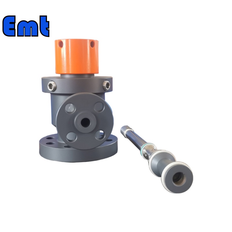
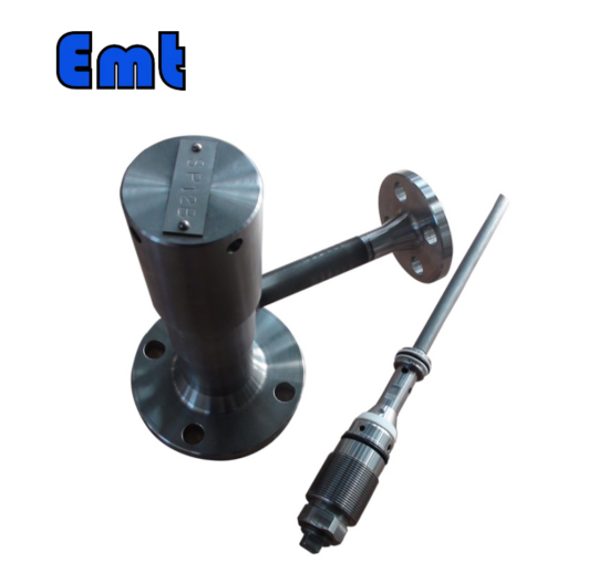
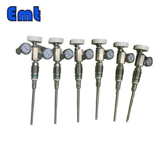
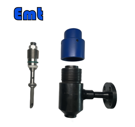
| Nom | Pipeline Plume d’injection chimique Système d’échantillonnage |
| Matériel | Acier inoxydable 304, acier inoxydable 316, DSS F51, acier au carbone A105N, Inconel 625 |
| Température de fonctionnement | -20±120 |
| Caractéristique | 1. Utilisation facile |
| 2. Longue durée de vie et haute précision | |
| 3. Haute efficacité, faible coût | |
| Paiement | TT/LC |
| Avantage | Tout d’abord, ils sont légers et flexibles. |
| Deuxièmement, une belle efficacité d’injection. | |
| Enfin un suivi précis de la localisation. |
Modèle de sélection
| Modèle | ||||||||||||||||||||||||||||
| SI | Plume d’injecteur chimique | |||||||||||||||||||||||||||
| -Code | Bouchon | |||||||||||||||||||||||||||
| Pxxx | Type | Matériel | Scellement Matériel | |||||||||||||||||||||||||
| 0 | Aucune demande | 0 | CS | 0 | Aucune demande | |||||||||||||||||||||||
| 1 | Creux Corps de la prise | 1 | 316SS | 3 | DSS | 1 | Joint torique Viton / Garniture primaire en PTFE | |||||||||||||||||||||
| 2 | Corps de prise solide | 2 | 316LSS | 4 | INCONEL | 2 | HNBR | |||||||||||||||||||||
| –Code | Écrou d’injection | |||||||||||||||||||||||||||
| Nxx | Taille de la connexion | Matériel | ||||||||||||||||||||||||||
| 0 | c’est-à-dire aucune demande | 0 | i.e. CS | |||||||||||||||||||||||||
| 1 | c’est-à-dire 1/4" | 1 | c’est-à-dire 316SS | 3 | c’est-à-dire le DSS | |||||||||||||||||||||||
| 2 | c’est-à-dire 1/2" | 2 | c’est-à-dire 316LSS | 4 | c’est-à-dire INCONEL | |||||||||||||||||||||||
| –Code | Injection Tube | |||||||||||||||||||||||||||
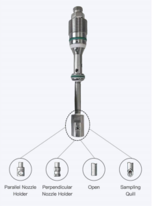
| Sxxx-Lx" | Taille de la connexion | Matériel | Buse | Taille de ligne (x") | ||||||||||||||||||||||||
| 0 | Aucune demande | 0 | CS | 0 | c’est-à-dire aucune demande | La position la plus efficace pour l’injection se situe généralement au centre du tuyau | ||||||||||||||||||||||
| 1 | c’est-à-dire 1/4" | 1 | c’est-à-dire 316SS | 1 | c’est-à-dire ouvert | |||||||||||||||||||||||
| 2 | c’est-à-dire 1/2" | 2 | c’est-à-dire 316LSS | 2 | c’est-à-dire Quill | |||||||||||||||||||||||
| 3 | c’est-à-dire le DSS | 3 | i.e. Cap & Core | |||||||||||||||||||||||||
| 4 | c’est-à-dire INCONEL | |||||||||||||||||||||||||||
| –Code | Mamelon et valve (ou extrémité bride) du té | |||||||||||||||||||||||||||
| Txx | Taille de la connexion | Matériel | ||||||||||||||||||||||||||
| 0 | c’est-à-dire aucune demande | 0 | i.e. CS | |||||||||||||||||||||||||
| 1 | c’est-à-dire mamelon de 1/4 po | un | c’est-à-dire mamelon et valve de 1/4 po | 1 | c’est-à-dire 316SS | |||||||||||||||||||||||
| 2 | c’est-à-dire mamelon de 1/2 po | b | c’est-à-dire mamelon et valve de 1/2 po | 2 | c’est-à-dire 316LSS | |||||||||||||||||||||||
| 3 | c’est-à-dire mamelon 3/4" | c | c’est-à-dire mamelon et valve 3/4" | 3 | c’est-à-dire D SS | |||||||||||||||||||||||
| 4 | c’est-à-dire 1" Mamelon | d | c’est-à-dire mamelon et valve de 1 po | 4 | c’est-à-dire INCONEL | |||||||||||||||||||||||
| 5 | c’est-à-dire bride 1/4" | e | c’est-à-dire 1/4" Bride d’extrémité de mamelon | |||||||||||||||||||||||||
| 6 | c’est-à-dire 1/2" Bride | f | c’est-à-dire 1/2 "Bride d’extrémité de mamelon | |||||||||||||||||||||||||
| 7 | c’est-à-dire bride 3/4" | g | c’est-à-dire 3/4 "Bride d’extrémité de mamelon | |||||||||||||||||||||||||
| 8 | c’est-à-dire bride de 1 " | h | c’est-à-dire 1" Bride d’extrémité de mamelon | |||||||||||||||||||||||||
| Par exemple, SI-P221-N12-S122-L4"-T22 | ||||||||||||||||||||||||||||
| SI:e.g. Sampling & Injection Assembly, | ||||||||||||||||||||||||||||
| P221 : par exemple corps de connecteur solide en joint torique Viton 316LSS et garniture primaire en PTFE, | ||||||||||||||||||||||||||||
| N12 : par exemple, la taille de la connexion de l’écrou d’injection est de 1/4 "et Le matériau est 316LSS, | ||||||||||||||||||||||||||||
| S122 :p. ex. injection Tube La taille de la connexion est de 1/4" et Le matériau est 316LSS. Le type de buse est des piquants | ||||||||||||||||||||||||||||
| L4 » :Pour tuyau de 4 ». | ||||||||||||||||||||||||||||
| T22 : Mamelon de la taille de la connexion en T est de 1/2", Le matériau de l’écrou est 316LSS | ||||||||||||||||||||||||||||
Principaux produits chimiques utilisés dans l’industrie pétrolière et gazière
Inhibiteurs de corrosion
Types et mécanismes de corrosion
La corrosion se présente sous diverses formes, notamment la corrosion galvanique, la corrosion par piqûres et la corrosion caverneuse. Chaque type provient de réactions électrochimiques ou chimiques distinctes. Ces réactions dégradent les métaux et compromettent l’intégrité des pipelines. La compréhension de ces mécanismes aide à sélectionner les inhibiteurs appropriés.
Rôle des inhibiteurs de corrosion dans la prévention de la corrosion
Les inhibiteurs de corrosion jouent un rôle essentiel dans la protection des surfaces métalliques. Ils forment une barrière qui minimise l’exposition du métal aux agents corrosifs. Ce faisant, ces inhibiteurs prolongent considérablement la durée de vie des équipements pétroliers. Le produit assure la continuité de fonctionnement et la sécurité.
Inhibiteurs de tartre
La formation de tartre résulte de la précipitation des minéraux dissous dans les fluides de production. Il affecte principalement les tuyaux et les vannes, entraînant des blocages et une réduction du débit. Par conséquent, l’échelle peut avoir un impact considérable sur l’efficacité opérationnelle et augmenter les coûts de maintenance.
Fonctions et applications des inhibiteurs de tartre
Les inhibiteurs de tartre empêchent le dépôt de tartre en interférant avec la cristallisation des minéraux. Ils sont essentiels au bon fonctionnement des pipelines et des équipements. Les opérateurs appliquent ces produits chimiques dans des zones sujettes à de fortes concentrations minérales, préservant ainsi l’efficacité du débit et réduisant les temps d’arrêt. Chaque application est essentielle pour éviter des interruptions coûteuses et améliorer la productivité globale de l’extraction de pétrole et de gaz.
Conclusion
L’injection chimique est une pierre angulaire de l’industrie pétrolière et gazière, assurant le bon fonctionnement et l’efficacité des activités d’extraction et de traitement. Il améliore considérablement l’efficacité de la production en s’attaquant de front à des problèmes tels que la corrosion et la formation de tartre. De plus, ces produits chimiques prolongent la durée de vie opérationnelle des infrastructures vitales, protégeant les investissements et favorisant la durabilité des opérations.
La mise en place de systèmes d’injection de produits chimiques efficaces offre de nombreux avantages. Tout d’abord, ils assurent l’intégrité et la longévité des systèmes de canalisations en empêchant la corrosion et l’accumulation de tartre. Deuxièmement, ces systèmes contribuent à une performance opérationnelle optimale, ce qui est crucial pour maintenir la productivité et réduire les temps d’arrêt. De plus, en gérant la qualité et l’uniformité de la production, les systèmes d’injection de produits chimiques aident à respecter les normes environnementales et de sécurité, améliorant ainsi la conformité globale de l’industrie. Enfin, l’utilisation stratégique de produits chimiques dans les opérations pétrolières et gazières augmente non seulement la rentabilité, mais soutient également l’engagement de l’industrie à l’égard d’une gestion responsable de l’environnement.


Il n’y a pas encore d’avis.