Introduction
Un injecteur de piquants est un outil essentiel qui révolutionne les systèmes de distribution de fluides. Il assure une précision inégalée dans l’injection de liquides. Cette précision est cruciale dans des industries telles que les produits pharmaceutiques, le pétrole et le gaz, et la transformation des aliments. Ici, même des inexactitudes mineures peuvent entraîner des problèmes majeurs. Les injecteurs de piquants résolvent ces problèmes en délivrant des volumes exacts de liquide. Ils le font à des vitesses contrôlées directement dans un flux de processus. Cette méthode améliore non seulement la qualité du produit, mais augmente également l’efficacité opérationnelle. De plus, il permet de maintenir la cohérence entre les lots. Alors que les industries s’efforcent d’obtenir des normes plus élevées et des réglementations plus strictes, le rôle des injecteurs de plumes devient encore plus vital. Ils fournissent une solution fiable qui répond à des exigences strictes. De plus, les injecteurs de plume aident à réduire les déchets et l’impact environnemental. Ils veillent à ce que chaque goutte de liquide remplisse sa fonction. Par conséquent, la compréhension et la mise en œuvre d’injecteurs de piquants peuvent améliorer considérablement les processus de production. Ils sont essentiels pour obtenir une précision dans l’administration des fluides.
Modèle de sélection
Nom | Assemblage de la plume d’injection | |
| Matériel | Acier inoxydable 304, acier inoxydable 316, DSS F51, acier au carbone A105N, et aussi Inconel 625 | |
| Température de fonctionnement | -20±120 | |
| Caractéristique | Tout d’abord, une utilisation facile | |
| Deuxièmement, haute précision et longue durée de vie | ||
| Enfin, haute efficacité, faible coût | ||
| Paiement | TT/LC | |
| Avantage | Tout d’abord, ils sont légers et flexibles. | |
| Deuxièmement, une excellente efficacité d’injection. | ||
| Enfin un suivi précis de la localisation. |
| Modèle | ||||||||||||||||||||||||||||
SI | Plume d’injecteur chimique | |||||||||||||||||||||||||||
| -Code | Bouchon | |||||||||||||||||||||||||||
| Pxxx | Type | Matériel | Scellement Matériel | |||||||||||||||||||||||||
| 0 | Aucune demande | 0 | CS | 0 | Aucune demande | |||||||||||||||||||||||
| 1 | Creux Corps de la prise | 1 | 316SS | 3 | DSS | 1 | Joint torique Viton / Garniture primaire en PTFE | |||||||||||||||||||||
| 2 | Corps de prise solide | 2 | 316LSS | 4 | INCONEL | 2 | HNBR | |||||||||||||||||||||
| –Code | Écrou d’injection | |||||||||||||||||||||||||||
| Nxx | Taille de la connexion | Matériel | ||||||||||||||||||||||||||
| 0 | c’est-à-dire aucune demande | 0 | i.e. CS | |||||||||||||||||||||||||
| 1 | c’est-à-dire 1/4" | 1 | c’est-à-dire 316SS | 3 | c’est-à-dire le DSS | |||||||||||||||||||||||
| 2 | c’est-à-dire 1/2" | 2 | c’est-à-dire 316LSS | 4 | c’est-à-dire INCONEL | |||||||||||||||||||||||
| –Code | Injection Tube | |||||||||||||||||||||||||||
| Sxxx-Lx" | Taille de la connexion | Matériel | Buse | Taille de ligne (x") | ||||||||||||||||||||||||
| 0 | Aucune demande | 0 | CS | 0 | c’est-à-dire aucune demande | La position la plus efficace pour l’injection se situe généralement au centre du tuyau | ||||||||||||||||||||||
| 1 | c’est-à-dire 1/4" | 1 | c’est-à-dire 316SS | 1 | c’est-à-dire ouvert | |||||||||||||||||||||||
| 2 | c’est-à-dire 1/2" | 2 | c’est-à-dire 316LSS | 2 | c’est-à-dire Quill | |||||||||||||||||||||||
| 3 | c’est-à-dire le DSS | 3 | i.e. Cap & Core | |||||||||||||||||||||||||
| 4 | c’est-à-dire INCONEL | |||||||||||||||||||||||||||
| –Code | Mamelon et valve(ou fin bride) du té | |||||||||||||||||||||||||||
| Txx | Taille de la connexion | Matériel | ||||||||||||||||||||||||||
| 0 | c’est-à-dire aucune demande | 0 | i.e. CS | |||||||||||||||||||||||||
| 1 | c’est-à-dire mamelon de 1/4 po | un | c’est-à-dire mamelon et valve de 1/4 po | 1 | c’est-à-dire 316SS | |||||||||||||||||||||||
| 2 | c’est-à-dire mamelon de 1/2 po | b | c’est-à-dire mamelon et valve de 1/2 po | 2 | c’est-à-dire 316LSS | |||||||||||||||||||||||
| 3 | c’est-à-dire mamelon 3/4" | c | c’est-à-dire mamelon et valve 3/4" | 3 | c’est-à-dire D SS | |||||||||||||||||||||||
| 4 | c’est-à-dire 1" Mamelon | d | c’est-à-dire mamelon et valve de 1 po | 4 | c’est-à-dire INCONEL | |||||||||||||||||||||||
| 5 | c’est-à-dire bride 1/4" | e | c’est-à-dire 1/4" Bride d’extrémité de mamelon | |||||||||||||||||||||||||
| 6 | c’est-à-dire 1/2" Bride | f | c’est-à-dire 1/2 "Bride d’extrémité de mamelon | |||||||||||||||||||||||||
| 7 | c’est-à-dire bride 3/4" | g | c’est-à-dire 3/4 "Bride d’extrémité de mamelon | |||||||||||||||||||||||||
| 8 | c’est-à-dire bride de 1 " | h | c’est-à-dire 1" Bride d’extrémité de mamelon | |||||||||||||||||||||||||
| Par exemple, SI-P221-N12-S122-L4"-T22 SI:e.g. Sampling & Injection Assembly, P221 : par exemple corps de connecteur solide en joint torique Viton 316LSS et garniture primaire en PTFE, N12 : par exemple, la taille de la connexion de l’écrou d’injection est de 1/4 "et le matériau est316LSS, S122 :p. ex. injection Tube La taille de la connexion est de 1/4" et Le matériau est 316LSS. Le type de buse est des piquants L4 » :Pour tuyau de 4 ». T22 : Mamelon de la taille de la connexion en T est de 1/2", Le matériau de l’écrou est 316LSS | ||||||||||||||||||||||||||||
Qu’est-ce qu’un injecteur de piquants ?
Un injecteur de piquants est un dispositif spécialisé qui injecte des fluides directement dans un système sous pression ou un pipeline. Il assure une grande précision et un contrôle dans la distribution des liquides. Cet outil est crucial dans les applications où un dosage et une distribution précis sont essentiels. Par exemple, dans le traitement chimique, une injection précise de fluide peut avoir un impact sur la qualité du produit final. De plus, les injecteurs à piquants permettent l’introduction de fluides sans perturber la pression du système. Cette capacité les distingue des méthodes d’injection traditionnelles.
Les injecteurs traditionnels nécessitent souvent une dépressurisation du système avant l’introduction du fluide. Ce processus peut prendre du temps et entraîner des inefficacités. En revanche, les injecteurs de plume fonctionnent sous la pression maximale du système. Ils maintiennent un fonctionnement continu sans qu’il soit nécessaire de les arrêter ou de les interrompre. Cette méthode permet non seulement de gagner du temps, mais aussi d’améliorer la productivité. De plus, les injecteurs de piquants minimisent le risque de contamination. Ils veillent à ce que des substances externes ne pénètrent pas dans le système pendant le processus d’injection.
Composants d’un injecteur de piquants
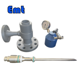
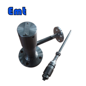
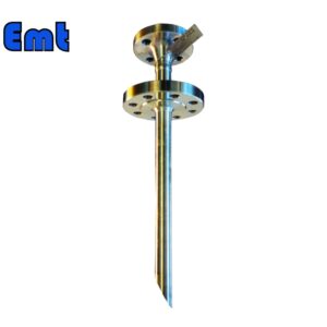
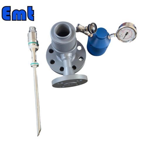
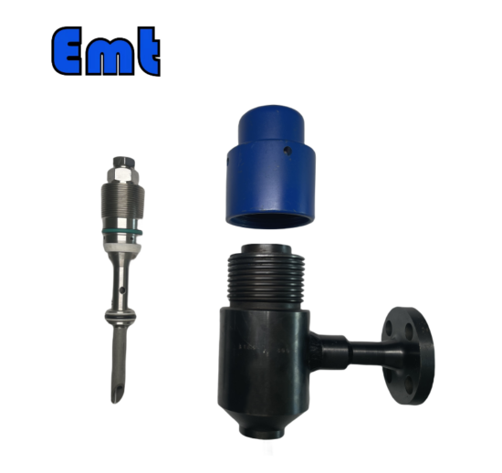
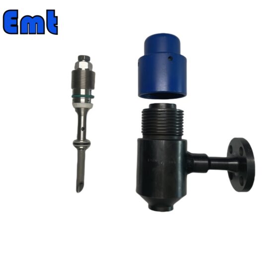
Comprendre les composants d’un injecteur de plume est essentiel pour apprécier sa fonctionnalité et son efficacité. Les pièces principales comprennent le corps, la buse et le clapet anti-retour. Chacun joue un rôle central dans le fonctionnement de l’injecteur.
- Corps: Le corps de l’injecteur de plume abrite les composants internes. Il est généralement fabriqué à partir de matériaux robustes comme l’acier inoxydable. Cela garantit la durabilité et la résistance aux produits chimiques agressifs.
- Buse: La buse est essentielle pour contrôler le débit et le modèle de pulvérisation du fluide injecté. Il peut être réglable pour s’adapter aux besoins spécifiques de l’application, ce qui permet un contrôle précis du processus d’injection.
- Clapet: Le clapet anti-retour empêche le reflux du fluide de processus dans le système d’injection. Ce composant est crucial pour maintenir l’intégrité et la pureté des fluides injectés et traités.
Les schémas de ces composants aident à illustrer leur conception et leur fonction. Ils permettent de comprendre visuellement comment chaque pièce contribue à l’efficacité globale de l’injecteur de piquants.
Types d’injecteurs de piquants
Les injecteurs de piquants sont disponibles en différents modèles, chacun adapté à des applications spécifiques. Comprendre les différents types et leurs avantages et inconvénients est essentiel pour choisir le bon injecteur.
- Injecteurs de piquants haute pression: Ils sont idéaux pour les systèmes où une distribution de fluide à haute pression est nécessaire. Ils peuvent résister à des pressions extrêmes, ce qui les rend adaptés aux environnements à fort stress. Cependant, ils ont tendance à être plus coûteux et nécessitent des routines d’entretien robustes.
- Injecteurs de piquants à faible volume: Ces injecteurs sont conçus pour une distribution précise de petits volumes de fluide. Ils offrent une précision exceptionnelle, ce qui est crucial dans des applications telles que les produits pharmaceutiques. En revanche, ils peuvent ne pas convenir aux applications industrielles à grande échelle.
- Injecteurs de piquants réglables: Ces injecteurs permettent d’ajuster le débit et la pression, offrant ainsi une flexibilité dans diverses applications. Bien qu’ils offrent une polyvalence, ils peuvent nécessiter des systèmes de contrôle plus sophistiqués.
Chaque type d’injecteur de piquants a ses avantages et ses inconvénients, en fonction des exigences spécifiques de l’application. Les injecteurs haute pression sont robustes mais coûteux, les injecteurs à faible volume sont précis mais à échelle limitée, et les injecteurs réglables sont polyvalents mais complexes. Pour choisir le bon type, il faut peser ces facteurs par rapport aux besoins du processus.


Il n’y a pas encore d’avis.