Introduction
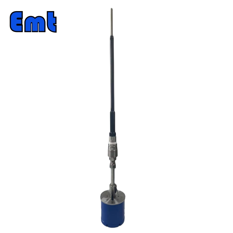
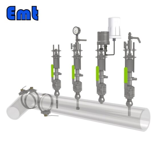
EMT ER Probe can be used to measure metal loss in many areas. It can provide online data about the corrosion rate in the system. The data can check the efficacy of corrosion inhibition or detect corrosivity changes in the system.
Applications of ER Probe
What applications are ER Probes suitable for?
They play a crucial role in most intrusive corrosion monitoring applications. The ER Probes are usable in almost any environment, being independent of the process properties.
What applications are ER Probes not suitable for?
ER Probes are not recommended for use in sour service because conductive (iron sulphide) scales are likely to be deposited.
Accessories of the EP Probe
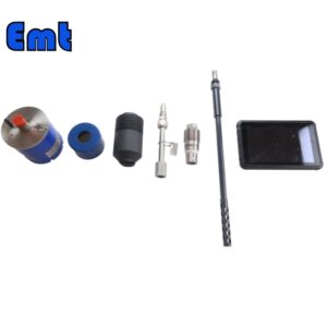
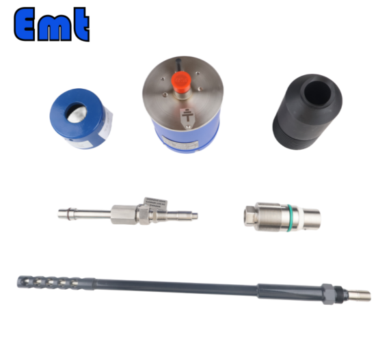
Corrosion Probe; Probe Adapter; Portable data logger; Wireless Transmitter; Base; Plug Assembly; Protective cover; Instrument Connector; Key position
Assembly of ER Corrosion Probe
Begin by attaching the plug assembly, identified by its white seal, to the probe. This seal fits between the plug and the base. Secure it by turning the counter-thread in the reverse direction and using a wrench to tighten it. Once done, insert this assembly into the base—usually welded to the pipeline—and secure it further. Cap it off with the protective cover.
For the second step, align the probe adapter’s notch with the probe’s key slot, join them together, and fasten the connection. Tighten the top nut to ensure the adapter remains stable during use.
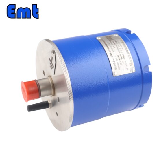
Next, set up the wireless transmitter, taking care to avoid any explosion-proof areas. Join the two white connectors; a flashing green light will indicate a successful power connection before it turns off. Shield the transmitter with its protective cover and transport it to the required location. Upon arrival, discard the red cap from the transmitter’s plug and connect it to the adapter’s matching key position. Secure it with the connecting nut, tightened with a wrench.
To finalize the setup, lock everything in place with a screw. With this last step, your equipment is fully installed and ready to use.
Usage of Portable Data Logger
Turn on the tablet PC and open the Bluetooth settings software. Watch as the driver software initiates and the device connects. Then, promptly minimize the settings window. Next, open the EMT software and adjust the settings to pair with the device. Click on the ‘device scanning’ option. Once the device connects successfully, click to stop the scanning process. Now, proceed to download the data. The software will present you with data from various periods, automatically generating a data curve. Click on the curve to examine the data in detail.
At the same time, take the opportunity to calculate the corrosion rate. To do this, select a data point to mark the start of the collection and another point to mark the end. Then, click on the ‘corrosion rate calculation’ button. A value will be displayed, and based on this value, you will determine the next step.
Selection Mode of ER Probe
| Type | |||||||||||||||
| ECP | Resistance Probe Assembly | ||||||||||||||
| ‐Code | Plug | ||||||||||||||
| Pxxx | Type | Material | Sealing material | ||||||||||||
| 0 | i.e. No Requirements | 0 | i.e. Carbon Steel | 0 | i.e. No Requirements | ||||||||||
| 1 | i.e. Hollow insert | 1 | i.e. 316 stainless steel | 1 | i.e. Fluorine rubber sealing ring/PTFE main seal | ||||||||||
| 2 | i.e. 316L stainless steel | 2 | i.e. Hydrogenated Nitrile | ||||||||||||
| 3 | i.e. F51 Duplex stainless steel | ||||||||||||||
| 4 | i.e. INCONEL Nickel based alloy | ||||||||||||||
| ‐Code | Temperature and pressure gauge components | ||||||||||||||
| Txxx | Connection size | Body Material | Temperature and pressure gauge material | ||||||||||||
| 0 | i.e. No Requirements | 0 | i.e. 304 stainless steel | 0 | i.e. No Requirements | ||||||||||
| 1 | i.e. 1/2″ | 1 | i.e. 316 stainless steel | 1 | i.e. 304 stainless steel | ||||||||||
| 2 | i.e. 3/4″ | 2 | i.e. 316L stainless steel | 2 | i.e. 316 stainless steel | ||||||||||
| 3 | i.e. F51 Duplex stainless | ||||||||||||||
| ‐Code | Probe Assembly | ||||||||||||||
| Dxx ‐Lx″ | Connection size | Body Material | Pipeline Specifications(‘’) | ||||||||||||
| 0 | i.e. No Requirements | 0 | i.e. stainless steel | Probe length varies with pipeline specifications | |||||||||||
| 1 | i.e. 1/4″ | 1 | i.e. 304 stainless steel | ||||||||||||
| 2 | i.e. 1/2″ | 2 | i.e. 304L stainless steel | ||||||||||||
| 3 | i.e. 316 stainless steel | ||||||||||||||
| 4 | i.e. 316L stainless steel | ||||||||||||||
| 5 | i.e. F51Duplex stainless | ||||||||||||||
| Example: ECP‐P121‐T021‐D01‐L6″ ECP: i.e.Resistance Probe Assembly; P131: i.e., the hollow insert material is 316L, with F51 Duplex stainless steel and polytetrafluoroethylene main steel. T111: i.e., the temperature and pressure gauge component connector size is 1/2 ″, and the material is 316 stainless steel. The temperature and pressure gauge are made of 304 stainless steel. D01: i.e.The probe connection size is not required, and the probe body material is 304 stainless steel; L8″: i.e.The probe length is suitable for 8 “pipelines | |||||||||||||||
Above is the selection mode of the EMT ER Probe. According to it, you can choose a specific model.
Conclusion
In conclusion, the EMT ER Probe is a versatile instrument for monitoring metal corrosion, adaptable to various environments, but unsuitable for sour services. Its components and assembly process facilitate efficient setup and data collection, while the portable data logger simplifies onsite corrosion analysis. The model selection mode ensures the customization of the probe to specific pipeline requirements.


There are no reviews yet.